Korg MS20 mini, first thoughts…

Right, first things first, the comments that follow are my own opinion and I have no connection with Korg.

OK with that out of the way, I recently bought my first new synth in years, a Korg MS20 mini. It is brilliant,,,

I needed a synth as a teaching aid as I am reluctant to take my EMS Synthi AKS out nowadays so the search was on for a modern analogue synth that could be used to introduce people to the principles of operation of an old-style analogue synth.

Intrigued by the idea that Korg were to release a new version of their MS20 I felt that it deserved some serious research into what they had created as a ‘new’ synth for 2013.

I duly visited my local keyboard shop where they have an MS20 mini on permanent demo (but none actually in stock!). I approached with an open mind to find that Korg have created a near perfect 89% sized replica of the original. The electronics are surface mount but as near as they could make to the original with modern components. They even used some of the development team of the original and I feel they have succeeded admirably.

Having put the demo model through its paces I concluded that this was the closest you could get to owning a new MS20 and that the scaling down aspect was not a problem. So I ordered one…

To my surprise the news came that a delivery was days rather than weeks away so last week I collected my first ‘new’ analogue synth in living memory.

As I stated earlier this synth was purchased as a teaching aid and for that purpose it is ideal as it is a synth with a fixed signal path but also has a small jack field to allow patching of some of the control voltages. Some of the functions will not work without patching so that encourages experiments.

However having spent some time with the MS20 mini I have concluded that it is one of the the best new (/old) synths I have seen or heard in years. The reason for this conclusion is that it sounds amazing, this is a synth with surprising depth and detail so instead of being a substitute for any synth I have already it actually brings some new sonic possibilities.

I wasn’t expecting that.

The final thought is that it actually brings analogue synthesis back to the masses as it makes good analogue synthesis within reach of many more people as it only costs £500 (the same price as a reasonable electric guitar). Compare that to the £1500+ being asked for an original MS20 from the 1970s.

Well done Korg, perhaps this is the beginning of an analogue synth revival…
SEM – wow…

Recently had a pair of rack mounted Oberheim SEMs to look at (SEM = Synthesiser Expander Module) which came to me a bit unwell. Main fault was that the filter on one of them had turned itself into a volume control.

Anyway powered up faulty module to check if anything else was wrong and was struck by how rich the oscillators were. Dammit this synth sounds really good EVEN WHEN IT IS BROKEN! As I had already studied the circuit diagram and had ordered some spare parts based on a description of the fault from the client it took less than an hour to fix. This was aided by the very neat design that puts pots and switches on one PCB and the electronics on a second PCB that plugs into the first via a number of multiway connectors. A couple of minutes with an oscilloscope confirmed that the fault was as expected, powered down and replaced prime suspect number one (a 3080 OTA in the filter) and bingo, up and running.

What a filter. On paper it should be weedy, only 12dB / octave but coupled with the previously described oscillators it sounded awesome. Reminded me a bit of the power of a set of Moog Taurus pedals.

Neat part of the SEM is the pot that allows you to go from Low pass to High pass filter vis Band pass. There is also a switch on the same pot that allows you to select Notch filter as well.

So the sad bit is that I passed on a beautiful example of an Oberheim 2 voice at a reasonable price which puts two SEMs and a splendid little Minisequencer all into a very neat package along with a 3 octave keyboard.

Oh well one for the shopping list…

Speech Synthesis – the early years…

Recently I got asked to recreate sound of the Voder for an art installation which meant I had to do some background research about speech synthesis and got a few surprises along the way…

First surprise: First speech synthesiser was developed in the 1770s by Wolfgang von Kempelen in Vienna!

Von Kempelen’s machine was the first that allowed to produce not only some speech sounds, but also whole words and short sentences. The machine consisted of a bellows that simulated the lungs and a ‘wind box’ that was provided with levers to be actuated with the fingers of the right hand. The levers actuated a ‘mouth’, made of rubber, there was also a ‘nose with two nostrils that had to be covered with two fingers unless a nasal sound was to be produced. The whole speech production mechanism was enclosed in a box with holes for the hands.

Second surprise: Wheatstone, developer of the Wheatstone Bridge (electrical engineers will know all about this) also experimented with speech synthesis.

Third surprise: The Voder was an instrument that you played. Homer Dudley at Bell Labs had been refining the idea that vocal sounds can be grouped into a fairly small number of pitched and un-pitched sounds that could be created electronically. For example letter “A” is pitched and the letter “S” is un-pitched. He also realised that the vocal chords were a “carrier” and that the lips, tongue, cheeks etc. were filtering the carrier to create all the different sounds required to produce speech. He reasoned that if these simulated sounds were then strung together in the correct order then speech could be created from scratch. His system used ten filters that could, if used in the correct combinations, create approximations of the most common vocal sounds. The (highly skilled) operator of the Voder had to manipulate 10 keys, a footpedal and wrist switches to create each of the sounds. Apparently it took about a year to become good enough to produce reasonable speech. The Voder was one of the attractions at the World Fair in New York in 1939, along with a robot that would smoke cigarettes!

So to make the Voder say “she saw me” you would have to do the following…

speech:             SH-E,       S- AW,       M-E

key:                 7&8  1&8    9     3        1   1,8

wrist lever:    up down    up down    down down

This was from the Voder instruction manual– Lesson 1,  no wonder it took over a year to get good at playing it…

So as you can see the Voder was effectively a vocoder that you manually ‘played’. Homer Dudley went on to develop the Vocoder which automates the analysis process by splitting the the input speech into the same bands as the keys on the Voder thus automating the process.

The principles of the Voder do live on in some modern equipment / systems. Adding a computer to the system it is possible to make text to speech converters that construct speech from text in real time. As a computer is doing the manipulation the intelligibility is much better and it is the system used by a number of up market Sat Nav systems  to read out street names.

Back on the case

Phew, long time since I’ve done an update as I have been incredibly busy mending stuff for the VEMIA auction and also working on a pet project for the last couple on months.

So now the prototype is out with a pro gigging musician I can spill some of the beans on what I’ve been up to…

Over the years I’ve built a number of fuzz / distortion devices so as I haven’t done one for a bit I felt it was time to do “the ultimate fuzzbox”.  However it took a bit longer than planned once I got into the history. First phase was to research the origins and development of the originals in the 1960s and to have a go at building a reasonable clone of the first one. OK so it “fuzzed” but to my ears it didn’t sound particularly musical. Early circuits used germanium transistors and as I have a bag of them that seemed a good starting place but that also was abandoned in favour of using modern silicon devices. So as you can see the brief was changing as I continued and became a circuit that I like the sound of using modern components.

Some original aspects have survived such as the use of discrete components, hand-wired onto tag-strip giving a distortion device with very low background noise. Sound is more organic.

Well you can get too close to your own creations so last week it was time to let some other guitarists have a go. Results were good as most people like the idea that the harder you play the more distortion you get. As I said earlier it’s now being tested at gig volumes and beyond.

Next step is to build a small number of pre-production examples and see how the finished article goes down.

The finished article will have more controls allowing the user to experiment with changing things like transistor bias and circuit configuration through some additional controls and switches.

Watch this space…

Traitor to the cause…

As you may have guessed I have an affinity for all things analogue so this next post could be a bit of a shock…

I’ve bought a digital synth that I think is brilliant! I have  been re-aquainting myself with my old Nord Modular (G1) so when I was offered a Nord Modular (G2) recently I decided that it was time to upgrade as the newer version had some important improvements that were worth having.

Firstly, you get a keyboard and some modulation controls. Secondly you get a better user interface (more displays). Thirdly, you have effects modules such as reverb and stereo delay. But that isn’t the whole story…

As a test of what could be done I considered how you could re-create something like a Novachord. The Novachord was the first polyphonic synth dating from the late 1930s with something like 160 odd valves in it with very crude controls but due to the way the oscillators work (one for each note in the top octave, then loads of divider circuits) everything sounds rather warm. The problem then was to recreate the subtle tuning discrepancies and other general vagueness as well as duplicating the restricted controls of the original.

Thinking the Nord wouldn’t be able to do this, I started patching away. First bit was easy, 12 voices, variable shape oscillator to create the core waveshape which was mainly sawtooth but a bit bent. The variable shape oscillator managed that, with an additional narrow pulse an octave above synched to the first oscillator to simulate the switching glitch caused by the dividers. So far so good. Next the scanner vibrato – a bit more of a challenge, basically the original is a number of very short delays derived from a chain of capacitors, a mechanical  switching system then determines how many delays are applied and the delayed signal is then summed with the original. Bit like a chorus pedal.

The filters of the Novachord were simple to replicate as they were all fixed. The filters were put in the FX area so only one instance of each for the entire instrument. The controls of the original were replicated by switching control values using fixed constant value modules to give the reduced resolution.

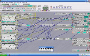
The entire patch - voices at the top, filters at the bottom.

Final problem was the vague tuning. That was achieved by combining the voice number output with a control sequencer to apply a small tuning offset to each voice. A similar arrangement was constructed to slightly offset the scanner speed as there was more than one scanner line in the original.

The only sad note here is that at the point that I discover (and buy) a Nord Modular G2, Clavia have decided to discontinue it. Shame…

Real or Virtual, you decide…

Some time ago I described how the humble ARP sequencer could be used as an improvisational tool.

Well recently I’ve been rediscovering my Nord Modular which is an odd mixture of real and virtual. The synth is real enough and consists of a DSP based synth that is programmed from an editor running on a PC. The clever bit is that the synth works even when the PC editor is disconnected.

I originally got the Nord Modular to replace my ARP 2600 that I had owned for 16 years as I thought it would be more versatile and take up less space. It is, especially good is the way you can create modules as required, so if a patch needs four sequencers you just keep dragging extra sequencers onto the edit window until you have enough or you run out of DSP capacity.

Anyway I recently was reading about the Klee Sequencer that is based on a shift register and the ability to sum certain outputs from shift register as it runs. The summed outputs are then used to control the notes played by some VCOs, just like a normal sequencer.

Having read up on the sequencer and just before I fired up the soldering iron (my weapon of choice) I thought “I wonder if I can construct a virtual sequencer from some of the virtual logic modules”. The answer is, yes.

Actually it did rather a good job (results can be heard on www.myspace.com/normleete). Just to give you an idea what the patch looks like here is a recent patch that attempts to emulate the David Vorhaus sequencer called the MANIAC. Here is David’s own description from an old Sound on Sound interview:-

“One of the first things I built was an analogue sequencer called the Maniac that plays as fast as you like, has variable step lengths and can be configured to do things other sequencers of the time couldn’t do. If you used it linearly it worked as a 64-step, duophonic sequencer, but I also built in the ability to split it into several smaller groups, which gave it the potential for cybernetic serendipity. For example, I might set one group to run around a sequence of seven steps and another eight steps, then add and subtract the control voltage outputs. That’s the great thing about voltage control, you can just add and subtract, so I might have one sequence running octaves and fifths with the other running passing notes. That means it would run for seven times eight, or 56 steps before repeating. I could chromatically correct the output if I wanted to. Incidentally, the name is an acronym for Multiphasic ANalog Inter-Active Cromataphonic (sequencer).”

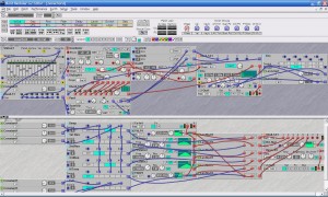
Nord Modular multi sequencer patch

The Nord patch is in an early phase of development but can do a lot of these features and does some splendid sequences that evolve over many minutes. This is still an active line of enquiry and the soldering iron is still cold…

Best of both worlds…

Ever wanted a synth that combines modular weirdness with practical musical usefulness, well a prime contender for this apparently dificult combination would be the ARP2600.

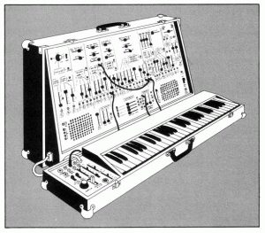
ARP 2600 (cover of Service Manual)
ARP 2600 (from cover of Service Manual)

So what makes the ARP 2600 so special? Some features of note include:-

  • VCOs that can be used as VCLFO’s (all three).
  • RING MOD that can be used as an additional VCA.
  • VCA with exponential response for percussion sounds that bite.
  • Excellent interfacing with external audio signals. Including an ENVELOPE FOLLOWER that can trigger the synth from external audio signals (cheesy drum machines are a good source).
  • NOISE SOURCE that goes right down to a rumble and can also be used as a modulation source.
  • VOLTAGE PROCESSORS that can do nearly anything to a control voltage coupled with excellent interfacing with external control sources such as a sequencer. (MIDI interfacing through a MIDI-CV converter is also very straight forward).
  • SAMPLE and HOLD that can accept inputs other than WHITE NOISE and that can be externally clocked.
  • Stability of tuning that is surprisingly good for it’s age and it is fairly easy to fix (although it rarely goes wrong).

ARP 2600 – History

The 2600 was Alan Richard Pearlman’s first attempt at a portable synthesizer following on from the massive ARP 2500 (as featured by Steven Spielberg at the end of ‘Close Encounters of the Third Kind’). To aid portability the instrument was in two parts, a console (31″ x 18″ x 9″) and a four octave keyboard (31″ x 6″ x 3″) each with a cover for protection during transportation.

Part of the company culture at ARP seemed to be “if Bob Moog does it then we don’t” which resulted in all fifty seven control pots being sliders and all eighty one jack sockets being 3.5mm. Some of ARP’s ideas cannot have been that bad because close examination of Roland modular gear such as the system 100 and the 100M shows remarkable similarities. I used Roland sequencers with my own 2600 for some years and can report that they are completely compatible.

The 2600 was one of ARP’s longest lived models. First produced in about 1971 (released at the same time as the rival Mini-Moog) it continued to be produced until ARP went out of business in 1981. During this long production run the 2600 went through several cosmetic and internal changes.

The first version was blue and has become known as the ‘Blue Meanie’. This (rarely seen) version has wooden handles and metal end cheeks. That version was quickly superceded (much to Alan Pearlman’s relief) by the tolex covered grey faced version that is most commonly seen. The ‘grey face’ 2600 went through two versions of keyboard, a simple monophonic version that was replaced by a duophonic keyboard (based on a design by Tom Oberheim). The final version (c.1978) was the ‘orange faced’ version that had a keyboard with PPC pads added to it to give additional perfomance controls (yes, some people did use these instruments for live performance!).

The front panel of the console is divided into ‘modules’ although unlike a true modular synth the panel is in one piece, the module layout is fixed and the modules are pre-patched already into a sensible configuration. However each ‘module’ still has inputs and outputs (using 3.5mm mini-jacks) so that patch-cords can be used to over-ride any of the default connections.

ARP 2600 – Features

The layout of the console is in eight vertical strips and one horizontal strip across the bottom. Starting from the left hand end the contents of the strips are as follows:-

  1. MICROPHONE PRE-AMPLIFIER with three gain ranges, ENVELOPE FOLLOWER that is pre-patched to the preamp output plus a RING MODULATOR with AC and DC coupling and inputs that are pre-patched to VCO1 and VCO2.
  2. VOLTAGE CONTROLLED OSCILLATOR VCO 1 with sawtooth and square wave outputs. There are modulation inputs from KBD, S/H OUT, ADSR and VCO2 (sine) all being fed into a CV mixer that is part of the VCO (another ARP innovation). Frequency can be controlled by coarse and fine sliders plus a switch that selects audio or LF mode. For all three VCO’s audio mode frequency range is between 10 Hz and 10 kHz without any reference to octaves. LF mode is between 0.03 Hz and 30 Hz.
  3. VCO 2 with sine, triangle, sawtooth and pulse outputs. There are modulation inputs from KBD, S/H OUT, ADSR and VCO1(square). Frequency can be controlled by coarse and fine sliders plus a switch that selects audio or LF mode. There is also a PWM control plus a PWM input pre-patched to the NOISE generator.
  4. VCO 3 with sawtooth and pulse outputs. There are modulation inputs from KBD, S/H OUT, ADSR and VCO2(sine). Frequency can be controlled by coarse and fine sliders plus a switch that selects audio or LF mode. There is also a manual PWM control.
  5. VOLTAGE CONTROLLED FILTER / RESONATOR VCF has coarse and fine sliders to control cutoff frequency plus a manual RESONANCE control. Audio inputs are pre-patched into a mixer that is part of the VCF. These inputs are from the RING MOD, VCO1(square), VCO2(pulse), VCO3(sawtooth) and the NOISE GEN. Modulation inputs are from the KBD CV, ADSR and VCO2(sine).
  6. ADSR and AR ENVELOPE TRANSIENT GENERATORS have such extras as a manual push button plus the ability to select the gate source. GATE and TRIGGER outputs are also available.
  7. VOLTAGE CONTROLLED AMPLIFIER has an initial gain contol plus modulation inputs from AR and ADSR. Unusually the sensitivities of the inputs are different, one is linear and the other is exponential. Audio inputs are from VCF and RING MOD.
  8. MIXER and REVERBERATOR has inputs from VCF and VCA and converts the mono output via a PAN control and a stereo reverb spring to stereo.

In the horizontal strip you will find:-

MULTIPLE (four jacks), KBD CV (output), LEFT SPEAKER (volume), NOISE GENERATOR(white though pink to low freq), VOLTAGE PROCESSOR(inverters, mixing plus a lag processor), SAMPLE and HOLD(with it’s own clock), ELECTRONIC SWITCH (bi-directional), RIGHT SPEAKER (volume), POWER (on / off) and STEREO PHONES (socket).A connector for the keyboard is on the left and mains in is on the right.

The earlier keyboard (3604) had only four rotary controls on it TUNE, PORTAMENTO, INTERVAL (fixed) and INTERVAL (variable). The second much better version (3620) had it’s own LFO (freeing VCO-2 for audio duties) with controls (all sliders) over LFO SPEED, VIBRATO DELAY and VIBRATO DEPTH. Additional features included keyboard CV’s for top and bottom notes, a PITCH BEND knob, PORTAMENTO controls plus TRIGGER MODE and REPEAT switches. The very late version of the 3620 added the rubber PPC control pads that first appeared on the Mark 2 Odyssey.

The 2600 has had some fairly famous users in its day and scanning any record collection credits between 1970 and the present day will often reveal ‘ARP 2600’. Some I have spotted include Genesis, Daniel Miller / Depeche Mode, Larry Fast, Steve Hillage, J-M Jarre, Weather Report, Who, Rod Argent, Klaus Schulze, Tangerine Dream and the Shamen to name a few.

Small, but perfectly formed…

Recently repaired one of the smallest analogue (in the main) synthesisers you will come across, the Yamaha CS01.

Yamaha CS01 in all it's simple glory

It can be the source of some very distinctive lead line sounds and is also great fun. This is synthesis at its most basic with only twenty controls (including the Mod and Pitch wheels) and 32 mini keys. There were two versions, the original CS01, released in 1982, which was metalic grey with a light blue labeling and the later CS01-II, released in 1984, that was mainly black with flourescent green lines and an upside down ‘YAMAHA’. I have seen a black version of the Mk1 and rumour has it that there was also an even less common version of the original version in red.

The voice architecture is a single ‘Voltage Controlled Oscillator’, Voltage Controlled Filter and a Voltage Controlled Amplifier with a single Envelope Generator and Low Frequency Oscillator as modulation sources. Having whipped the back off one I have my doubts that the VCO is analogue although the rest of the circuitry looks pretty conventional.

The layout of the front panel from left to right is as follows:-

Controllers: Directly to the left of the keyboard, where you would expect the performance controls, is the Power/Volume control plus the Breath Controller sensitivity controls for VCA and VCF. The Pitch Bend and Modulation wheels are at the back of the panel to the left of the keyboard with a modulation destination switch below them. This switch selects where the LFO output goes, to VCO or the VCF. Sadly the Pitch Bend is only up (sharp).

Behind the 32 note mini key (F-C) top note priority keyboard are the rest of the controls laid out in seperate sections, they are all sliders or switches that look like sliders.

LFO: First up is the ‘LFO Speed’ control. The LFO wave shape is a triangle shape only with a range of 0.5Hz – 10Hz.

VCO: The VCO section has five controls, Glissando, Pitch, Feet, Wave and PWM Speed. Glissando, instead of portamento is another giveaway that the VCO is digital although at the faster speeds the effect is virtually identical to portamento (thankfully). Pitch is a fine tune control with a range of plus or minus a semitone. Feet is a slider control with five stops, 4′, 8′, 16′, 32′ and WN which replaces the current VCO waveshape with white noise (that has no pitch). Wave is also a five way switch that selects Triangle, Sawtooth, Square, Fixed Pulse and Pulse Width Modulated waveshapes. The PWM Speed slider controls the speed of the dedicated PWM LFO (nice idea…).

VCF: Next is the VCF Cutoff Frequency slider that controls the cutoff of the fairly weak, 12dB / octave, VCF. Worse still the Resonance control is a two position switch (on the original) that selects resonance low or high. Thankfully this was replaced on the CS01-II with a proper slider and the VCF was also beefed up. Finally there is an EG Depth slider that behaves as expected.

VCA: has an EG Depth control that is a single slider that controls the effect that the EG has on the VCA .

EG: Finally there is a conventional ADSR envelope with a slider for each segment of the envelope.

On the left hand end is a socket for a Yamaha BC1 breath controller and on the right hand end are sockets for Line Out, Phones and a nine volt half-brick (power supply).

The last two inches of the front panel are taken up by a small speaker that can be used for monitoring the sound. As the CS01 can be powered by six ‘AA’ batteries this makes it completely portable and it can be used anywhere. This portability is one of the keys to the success of the instrument. If you use the line out socket (thus muting the internal speaker) and attach a guitar strap to the thoughtfully positioned strap buttons we are now into the ‘stroll around, pose like crazy, Jan Hammer school of playing and great fun it is too! The weird positioning of the perfomance controls now make sense as you just curl your fingers round the rear of the case to reach them and even the upside down ‘Yamaha’ on the CS01-II now looks right.

So whats all the fuss about? Well once freed from the constraints of the tiny internal speaker the instrument sounds quite powerful through a decent set of speakers. Coupled with the BC1 breath contoller the expression that can be added to lead lines is quite amazing considering the simplicity of the voice architecture. However the down side is that you look a complete (dribbling) prat while using it which is perhaps that is why the breath controller never caught on.

Because some people think these are toys (and not a true synthesiser) means there are bargains to be had. Sometimes found in car boot sales amongst other mini-keyed home keyboards you may pick one up for virtually nothing (I only paid twenty five quid for mine) and for my money that was an absolute steal.

If you see one cheap – buy it…

FM Synthesis – an overview…

The Yamaha DX7 (Mk 1) may be thought by some to be an unusual candidate for these pages as it can hardly be classed as a rare, collectable vintage analogue keyboard (however my point of view is that keyboards are to be played, not collected). But as it was originally produced in 1983 and was the first affordable digital synthesizer then now seems as good a time as any for a re-appraisal of this enigmatic keyboard. I say enigmatic as I am sure that a vast number of current and past owners of DX7’s probably never will understand how they work.

I still find that this is the keyboard for percussive bell sounds, excellent electric pianos and extreme bass sounds. For the rest of the time (with the Special Edition ROM) it makes an excellent master keyboard. However for real in depth FM search out the SY77 or it’s module equivalent, the TG77.

The DX7 was first produced in 1983 (after several years of apparent inactivity from Yamaha on the synth front) it followed the extremely expensive and completely preset GS1 and GS2 and took the synth market by storm. This was for several reasons, firstly it sounded good out of the box with sound that were less ‘electronic’ than other synths, secondly it was touch sensitive (with a decent keyboard to match), thirdly it was affordable (£1500 / $1800 approx). For these reasons it was soon the keyboard to be seen with during the mid-eighties and was so popular it even got a second chance with the DX7 MkII (not many synths get that honour). In total Yamaha went on to make something like 160,000 of them. As Yamaha held the patents on FM (developed by Professor John Chowning at Stamford University, USA) they went on to make about every possible flavour of FM synth from the portable DX100 through to the massive (professionals only) DX1. The range consisted of:-

  • DX1 – Voice structure of two DX7’s but with larger LCD and better user interface, seperate controls for envelopes, weighted 73 note keyboard with poly-aftertouch, high quality wooden case and a list price of 9500. A true professional’s instrument.
  • DX5 – similar in function to a DX1 but in a more conventional case (like a larger version of the DX7). With a 76 keys, this time without the poly-aftertouch, this instrument is still a large keyboard but in my opinion if you had the space for it this is an ideal studio master keyboard and it is easier to understand than the DX7 because of the improved control layout. A bargain especially at the sort of silly prices you sometimes see them go for second-hand.
  • DX7 – The ideal all rounder of the range for both studio and live.
  • DX7-IID – Not a simple upgrade but a complete range of redesigns, only loosely based on the success of the original, that was released in 1987. One version, the DX7-IIFD, included a floppy disc drive for voice parameter storage. The DX7S was also released at the same time for the semi-pro market which was nearer to a straight re-hash of the original DX7 (complete with small LCD, although it was back-lit this time). A module (19″ rack mount this time) called a TX802 was also made available.
  • DX9 – same size and case as a DX7, this original partner to the DX7 was an odd part of the range as it was a four operator synth without velocity. This makes it much easier to understand but also eventually quite limited. Expect to pick one up for next to nothing, although I personally would go for a DX21 or DX11 for a cheap 4 operator FM synth.
  • DX11 – part of the third wave of FM synths, a much more compact keyboard and now multi-timbral. Effectively a keyboard version of the TX81Z module, which strangely came out long before the DX11. Four operator but with additional waveforms other than sine waves, this is the best bet of the cheaper FM synths.
  • DX21 – Part of the second wave of FM synths. At this point Yamaha had seemed to have decided that no-one was going to get the hang of programming these synths so they included 128 sounds in ROM that could be retrieved into the normal program locations. Only four operator the DX21 could, for the first time on an FM synth, produce splits and layers as well as having a chorus. Sadly velocity could only be sent via MIDI, as the keyboard fitted was not capable of sensing velocity itself.
  • DX27 – similar to the DX21 but without the split / layer facility. 192 presets in ROM that could be accessed directly and only needed to be put into user RAM if edited.
  • DX100 – mini-key version of the DX27 and could be used as a strap on MIDI remote keyboard, complete with conveniently placed real time controllers that fell to hand when being played standing up. Great fun – used to have one and regret selling it now.
  • TX816 – Has to be mentioned for the total overkill factor as this was a 19″ rack mount setup with eight TF1 modules in it, each module was equivalent to a DX7. The only time I ever had a chance to use one of these it was being driven by a DX7 so that was equivalent to NINE seperate DX7’s! As each TF1 can remember a tuning offset then calling up a patch on the DX7 controlling the rack would, through sysex, put the same patch in each TF1 but with the tuning offset intact. This results in truly monstrous sounds. Was also available as the TX216 with just two TF1 modules.
  • V50 – odd one out as although not a synth with ‘DX’ in it’s model number this was the last of the pure FM synths and the only one that was a workstation. In effect this was two DX11’s plus a drum machine, sequencer, disc recorder and effects.

Although Yamaha no longer produce a pure FM synth elements of FM turn up in some of their newer products. The range is diverse with some lower end products such as the SY35, TG33 as well as some of the high end products such as the SY77, SY99 and TG77.

It should be noted that the SY77 and TG77 (the one I still use) was one of the few FM synths that also had a filter, allowing you to filter the results of the FM synthesis section (these two synths also have sample based AWM sources as well).

The principle of operation of all DX keyboards, including the DX7, is called FM (which stand for Frequency Modulation) and the principles on which is based are remarkably simple. A practical example will help. Take ANY analogue synthesiser and patch a single VCO to the VCF, select a waveform that is low in harmonic content (on most synths this will be a triangle) and set the VCF so that it has no effect (ie Frequency = max, Resonance = min, all modulation = zero). Set the VCA / Envelope controls to give an organ style envelope. This is probably the most ‘bland’ sound you have ever programmed but this is equivalent to a DX7 carrier (the carrier is the sound that you can hear). If you now patch the LFO into the VCO at a speed of about 7Hz a pleasant vibrato should result (the LFO is equivalent to a DX7 modulator). This is FM at sub audio and is perceived by the ear / brain system as vibrato (no surprises yet). As the rate of the LFO is increased then the the change in the sound becomes perceived as a change of timbre instead of a change of pitch (this will depend on the frequecy range of your LFO). If you can patch another VCO (also sine / triangle) into the modulation input of the first VCO (often labelled ‘Cross-Mod’, ‘Poly-Mod’ or ‘X-Mod’) instead of the LFO then you will find this is a source of some fairly alarming bell like noises whose timbre depends on the relative volumes and frequencies of the two VCO’s. A similar effect can be extracted from a self-oscillating VCF (a sine wave) being modulated by a VCO (sine or triangle). If you actually get round to trying this you will find that the resulting two oscillator system is fairly unstable and unpredictable (but good fun).

DX7 Operators - Modulator / Carrier pair

Diagram showing a pair of DX7 operators in a Modulator / Carrier configuration

But what has this to do with the DX7? Well as mentioned earlier the basic building block of any FM synth is the ‘operator’ which is a sine oscillator / envelope combination whose frequency can be controlled by the keyboard or by other operators. An important thing to note is that the operator is generated digitally so it’s behaviour is very predictable. This is important when these operators are made to interact with each other (remember the instability of the VCO’s in the above experiment). The way these operators (there are six on a DX7) are connected to each other are known as ‘algorithms’ and Yamaha saw fit to provide thirty two (although there are many more possible combinations thirty two seem to be enough to be getting on with).

Algorithm Example

Algorithm Example – see text for explanation

So how do you put all this together? Well lets take an example, something like an electric piano (which the DX7 is quite good at!). First you select your algorithm. This is decided by the type of sound you wish to produce, in our example we wish to produce the ‘thud’ of the hammer followed by a fairly pure, but warm, tone that reacts to keyboard velocity. To do this you choose an algorithm that has the constituent parts you need. I would suggest number 5 (see diagram above) as it has three pairs of operators all in a simple carrier / modulator set up. This allows us to have a sound with three constituent parts, the ‘thud’ is produced by operator pair 5 plus 6 with operator pairs 1 plus 2 and 3 plus 4 producing the warm chorused fundamental. Operator 5 and 6 are used for the thud as operator 6 has the feedback loop around it that allows unstable waveforms such as noise to be produced. As the thud is unpitched then the operators are set with a fixed frequency relationship and are not controlled by the keyboard. the envelope of operator 5 (the carrier) is adjusted to give a small click for the attack of each note. The envelope, level and feedback of operator 6 (the modulator) are adjusted to give the correct tonal quality to the thud. Once happy with the ‘thud’ the two operators responsible can be muted temporarily and the body of the sound can then be worked on. This is created by having a carrier envelope that is longer in duration than the modulator envelope which results in a sound that emulates the harmonic content of a struck tine. Using the copy function it is very simple to create two pairs of operators with the same parameters and then use the fine tune parameter to get the two ‘virtual tines’ to beat and sound less clinical. By using velocity sensitivity on the modulator levels then the timbre of the instrument can be made velocity dependent (just like a real electric piano). This is the secret of the success of the DX7 that also makes it a very difficult keyboard to sample correctly (it is also the reason why I still have an FM synth) as you can create sounds that vary in character in a most unpredictable way dependent on keyboard velocity.

This cannot be a complete description of how to program FM (that would take a complete book) but if you have a DX here are a few different things to try:-

1. For fatter “analogue” pads use a fixed frequency sub-audio carrier.

2. For “vocal” formants use a fixed (audio) frequency modulator, somewhere in the middle of a stack of operators.

3. Subtle use of the pitch envelope can be used to enhance the attack phase of a note (good for wind instrument emulations).

4. White noise and decent analogue sawtooth sound can be obtained from use of operator feedback.

5. Envelope bias can give the effect of an opening filter if applied to modulator sustain levels.

Best Synth ever?

OK, taking a risk here but here is my candidate for the best synth ever, you may disagree…

Mini Moog.

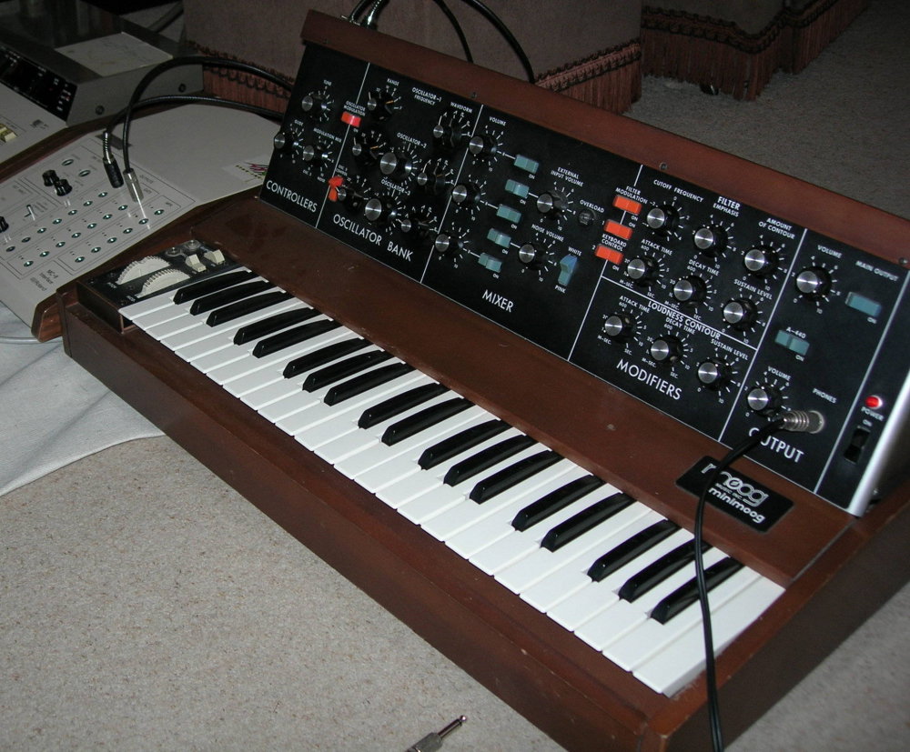
My MiniMoog being used to test a Roland MC8 I had just repaired

There, I’ve said it, but perhaps I should add some justification for such a bold statement.

The Mini Moog has become a synthesiser icon and as such has become steeped in folklore and legend, people boast of it’s prowess and it has become the synth to be seen with. This is unfortunate because in the wrong hands it is not an all rounder and can cause disappoinment (I am sure this is the source of quite a few secondhand or unused Mini Moogs).

To fully understand the Mini Moog you must ask yourself the question, why did Bob Moog and his team design it? If you consider what synthesisers were like in about 1968-69 they certainly were not designed for live performance. So I think his intention was to produce a synthesiser OPTIMISED for live performance. If you view a Mini Moog from this perspective and compare it with something contemporary such as the ARP2600 I think he succeeded. If I had to choose between the two then I would plump for the Mini Moog as I consider it to be a true musical instrument and not some sort of ‘sound lab’ (I had an ARP2600 for many years but when I had to make the difficult choice it was the ARP that was reluctantly sold).

The way the main panel hinges up, the space around controls, the clear layout and the large white lettering all assist rapid patching in the four bars leading up to your searing lead synth solo on a dimly lit stage. For such solos the Mini Moog has all the performance controls needed (the first synth to have mod and pitch wheels).

The main features in more detail…

CONTROLLERS: To the left of the 44 note F-C keyboard are pitchbend and modulation wheels plus on / off switches for glide (portamento) and decay. On the hinged front panel are Tune (used quite often!) the Glide control and Modulation mix. The modulation mix allows any combination of VCO 3 and the noise to be used as the modulation source.

OSCILLATOR BANK: Three VCO’s; VCO’s 1 and 2 having triangle, triangular sawtooth, sawtooth, square, wide rectangular and narrow rectangular waveshapes. VCO 3 replaces the triangular sawtooth with a reverse sawtooth that is more useful as a modulation source. VCO’s 2 and 3 have additional tune controls (plus or minus a fifth) and all three oscillators have a six way pitch switch (32′ – 2′ plus ‘LO’). VCO 3 can be disconnected from the keyboard CV while it is being used as a normal LFO. Oscillator tuning is quite an issue on these instruments and varies between examples because of component tolerances. Later examples have a different oscillator board that is much more stable once it has warmed up (critical parts of the circuitry are heated). Earlier examples (before 10175) have a mainly transistor based design whose stability can questionable (although I know one early example whose tuning is perfect). If you are thinking of buying one check the stability of over a period of about twenty minutes and see if it settles down by comparing it with the (handy) built in 440Hz tuning reference.

MIXER: Five input mixer with a level control and mute switch for each input. Inputs are form the oscillator bank, an external audio input and a white / pink noise source. The audio input also features the brightest overload indicator you will probably ever see!

MODIFIERS :The output of the mixer is hardwired into a 24dB / octave (classic transistor ladder design) with cutoff frequency and emphasis (resonance) controls. There is also a depth control for the dedicated ‘filter contour’ (envelope generator). Keyboard tracking is handled by two switches giving off, 1/3V / octave, 2/3V / octave and 1V /octave, The output of the VCF goes directly to the VCA that has its own dedicated ‘loudness contour’. The envelope generators are both a slightly unusual attack, decay, release design where the decay control determines both the initial decay and release rate. The previously mentioned decay on / off switch forces the release to zero when off. A strange idea but not as bad as it sounds once you get used to it!

OUTPUT: Has a main output control plus mute, a headphone socket and level control and a switch that adds a calibrated 440Hz tone to the output to assist tuning the instrument (also used quite often!). Finally there is a mains switch and indicator.On the top edge of the hinged rear panel are all the input and output sockets. Curiously missing is a keyboard CV output (although this can be added by the technically adventurous).

The MiniMoog is also capable of many more subtle and various sounds. This is because the clever way VCO3 can be used as a modulation source giving you a multi waveform VCLFO that can also modulate at audio frequencies (FM fifteen years before Yamaha!). External audio sources can be modified (Tangerine Dream often fed a Mellotron through a swept Moog filter). All VCO’s can be used as sub-audio sources that can be used to great effect on a filter that is near to self oscillation. You can even feed the output back into the external input if subtlety is not your scene for some of the most industrial (and scary) noises you will probably ever hear. If you are nervous about abusing your MiniMoog with the feedback trick you can get some very similar sounds by modulating the filter at audio frequencies with VCO3’s triangle wave (keyboard control must be on).

So there you have it , in my opinion, one of the best designed synthesisers ever manufactured and if I was forced to choose just one synthesiser to own then this would be it.

Mellotrons, Synths and electronics in music